Mastering EMC One Level at a Time
LEVEL 6 - Crosstalk in Transmission Lines
Crosstalk is a term commonly used to describe the unintentional electromagnetic coupling between two circuits or systems in close proximity. We have been using the formula,
,
to quantify this coupling, but it is important to note that there is no standard method for quantifying or calculating crosstalk. The expression above is convenient when describing the crosstalk between two identical linear circuits in the frequency domain. However, it can be problematic when applied to time domain waveforms, where very different results are obtained depending on whether the peak, peak-to-peak, or rms voltage is used. Also, the use of decibel notation is questionable when the voltage in the numerator and the voltage in the denominator appear across different impedances. In this section, which deals with crosstalk in transmission lines, we will continue to use the equation above to quantify crosstalk between two identical circuits in the frequency domain. For time-domain crosstalk calculations, and for crosstalk in circuits with different impedances, we will simply calculate coupled voltages.
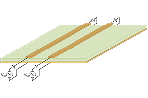
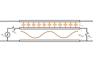
Here are a few laboratory exercises you can complete that will help you get familiar with measuring signals in the time and frequency domains.
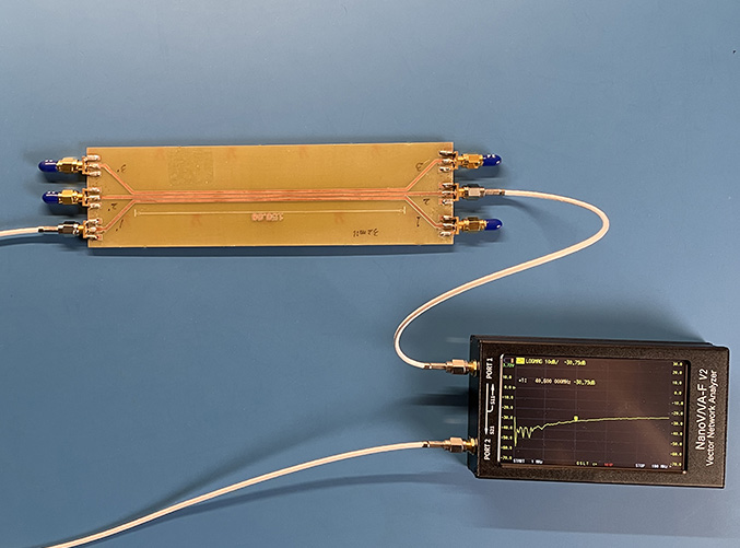
Lab Exercise 14-1: Measuring Frequency-Domain Crosstalk between Microstrip Traces
This exercise demonstrates how to make measurements of the near-end and far-end crosstalk between microstrip circuit board traces in the frequency domain.
Laboratory Exercise 14-1: Measuring Crosstalk Between Microstrip Traces
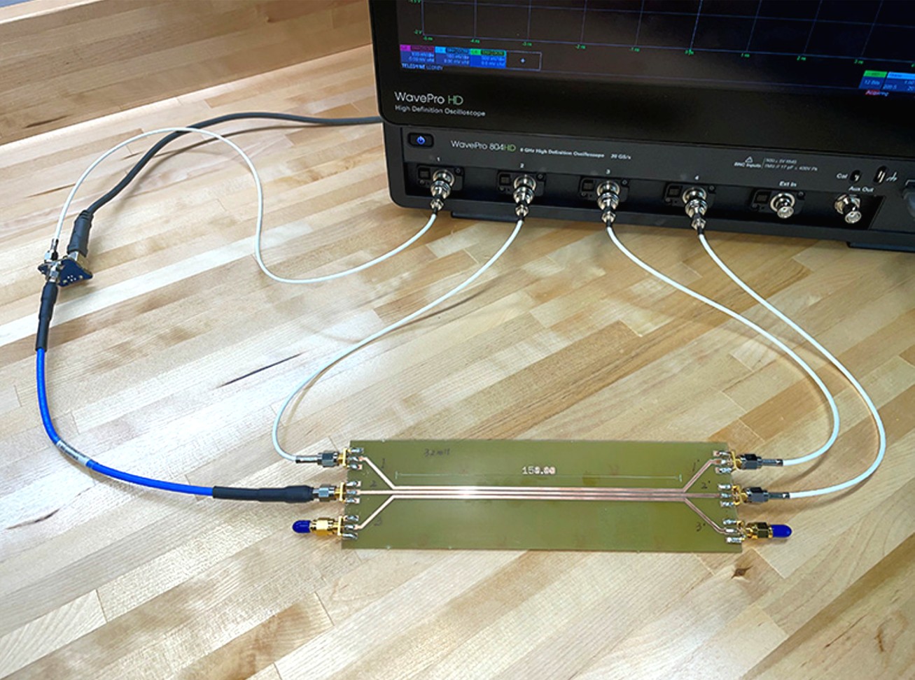
Lab Exercise 14-2: Measuring Time-Domain Crosstalk between Microstrip Traces
This exercise demonstrates how to make measurements of the near-end and far-end crosstalk between microstrip circuit board traces in the time domain.
Laboratory Exercise 14-2: Measuring Time-Domain Crosstalk Between Microstrip Traces
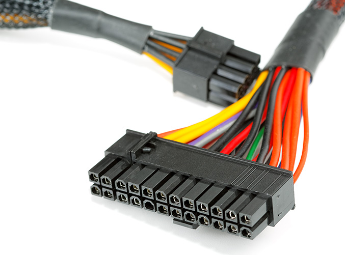
Lab Exercise 15: Measuring Crosstalk in a Cable Harness
This exercise demonstrates how to make measurements of the near-end and far-end crosstalk between signal conductors in a wire harness.
Laboratory Exercise 15: Measuring Crosstalk in a Cable Harness