
Chapter 10 Exercise: Electric-field Shielding
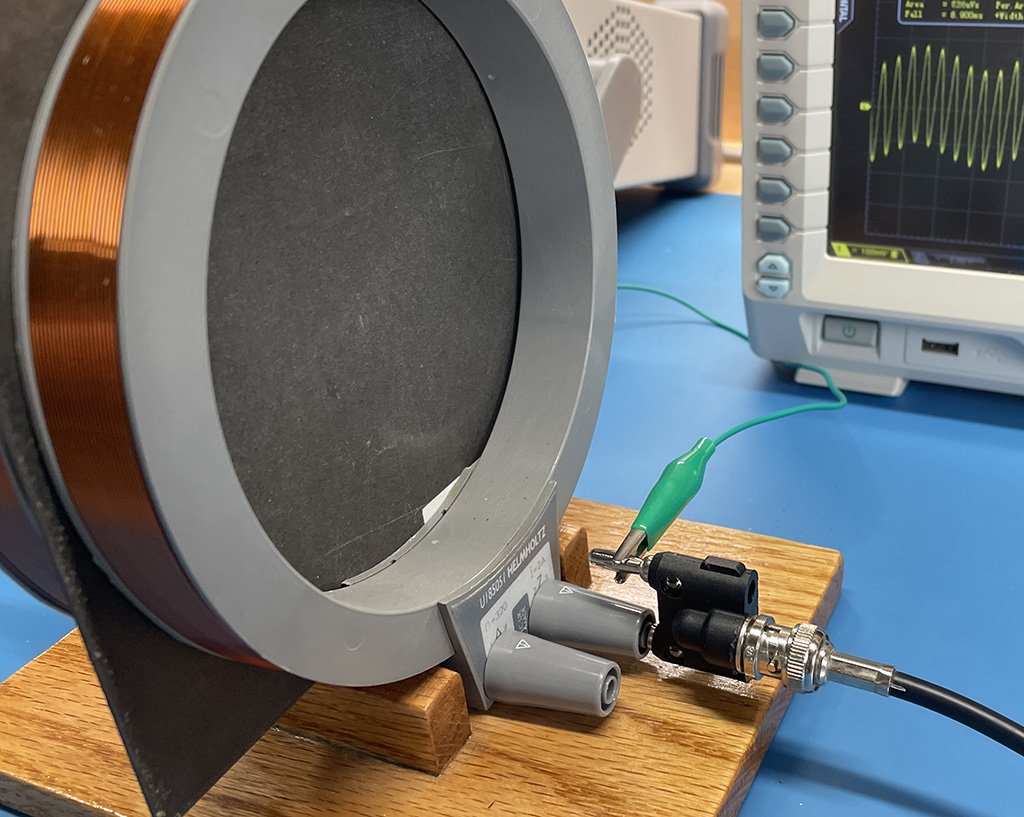
Unlike magnetic-field shielding, electric-field shields can terminate the field lines. Conductivity is important, but the thickness of the material is relatively unimportant.
Preparation: This lab can use the same fixture that was used for the magnetic field shielding labs. In this case, the coils are open-circuited so that they are driven with a voltage, but no current. The coils form surfaces that are driven by the voltage from the waveform generator. The electric-field coupling between the coils is responsible for the measured waveform on the oscilloscope.
Equipment Required:
- sinusoidal waveform generator (100 Hz - 100 kHz)
- oscilloscope
- test fixture comprised of two coils (or plates)
- samples of various materials (conductive and non-conductive, magnetic and non-magnetic)
Procedure:
Step 1: Connect the center conductor of the signal generator cable to the first coil and the center conductor of the oscilloscope cable to the second coil. Use a lead with clips to connect the outer (ground) conductors to each other. The coils behave like the plates of a capacitor. The signal measured by the oscilloscope represents the amount of electric-field coupling between the coils.
Step 2: Set the waveform generator to produce a 100-Hz sinusoidal signal. Adjust the oscilloscope until it shows a clean sinusoidal signal with an amplitude that nearly fills the screen. (It may be helpful to use the oscilloscope's internal bandwidth limiting to reduce the high-frequency noise picked up from other sources in the building.)
Step 3: Place a material sample between the two coils and note the amplitude of the received voltage with and without the material in place. Record the attenuation in decibels.
Step 4: Use another lead with alligator clips to connect the material to the signal ground conductor. Record the attenuation in decibels.
Step 4: Repeat the previous step for each of the sample materials.
Step 5: Make a table showing each of the materials and its respective attenuation (grounded and ungrounded). What do the materials with the highest attenuation have in common?
Step 6: Try attaching the permanent magnet to each of the materials. Add another column to the table indicating whether or not each material was attracted to the magnet.
Step 7: Repeat these measurements at 1 kHz, 10 kHz and 100 kHz.
Notes:
In this setup, only good conductors with a ground connection will make good electric-field shields.