
Chapter 10 Exercise: High-frequency Magnetic-field Shielding
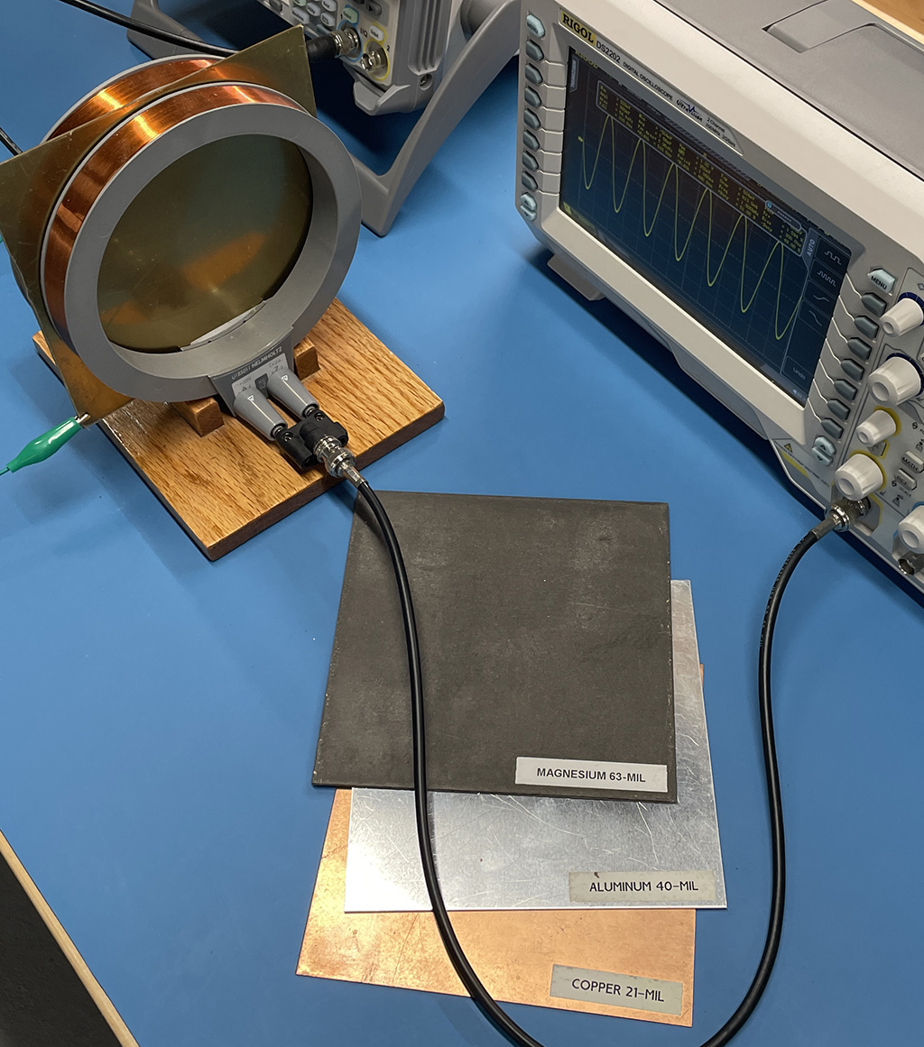
Lines of magnetic flux don't start or stop; they form loops. Magnetic field shielding doesn't stop the field; it redirects it. This lab investigates the ability of various materials to redirect a high-frequency magnetic field.
Preparation: This lab should be done immediately following the low-frequency magnetic shielding lab. It uses the same equipment at a higher frequency.
Equipment Required:
- sinusoidal waveform generator (1 kHz - 100 kHz)
- oscilloscope
- test fixture comprised of two coils with strong magnetic-field coupling
- samples of various materials (conductive and non-conductive, magnetic and non-magnetic)
- permanent magnet
Procedure:
Step 1: Connect the signal generator to the first coil and the oscilloscope to the second coil. The coils should be positioned to maximize the magnetic field coupling, but with a gap between them to allow the insertion of the shielding material samples.
Step 2: Adjust the oscilloscope until it shows a clean sinusoidal 1-kHz signal with an amplitude that nearly fills the screen.
Step 3: Place a material sample between the two coils and note the amplitude of the received voltage with and without the material in place. Record the attenuation in decibels.
Step 4: Repeat the previous step for each of the sample materials.
Step 5: Make a table showing each of the materials and its respective attenuation. What do the materials with the highest attenuation have in common?
Step 6: Repeat the measurements above at 10 kHz. Is the amplitude with no material a factor of 10 higher than at 1 kHz? How much did the attenuation of each material change from 1 kHz to 10 kHz?
Step 7: Cut a slot from the edge to the center of one of the materials with good attenuation. How does this affect the measured attenuation? Why?
Step 8: Repeat the measurements above at 100 kHz. Is the amplitude with no material a factor of 10 higher than at 10 kHz? How much did the attenuation of each material change from 10 kHz to 100 kHz?
Step 9: Using a lead with alligator clips, connect the material to the ground side of the source signal. Does it make a difference in the attenuation?
Notes:
If the magnetic coupling dominates, the ground connection should make no difference.
It is helpful to have various thicknesses of one or more of the conductive materials among the test samples. Thicker samples will start exhibiting attenuation at lower frequencies than the thinner materials due to the lower resistance they present to the eddy currents.