
Chapter 9 Exercise: Designing and Building a Common-Mode Filter
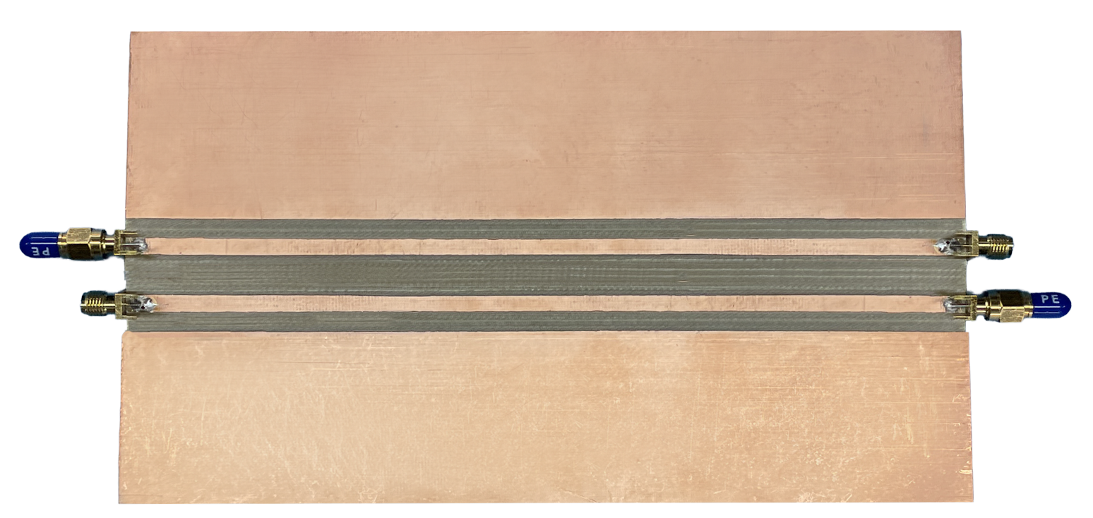
Students design and build a common-mode filter. This exercise requires a test fixture similar to the one shown in the figure on the right. It consists of two parallel 50-Ω microstrip traces with SMA connectors on both ends.
Preparation: Students will be given a set of design parameters that their filter should meet. For example, "differential-mode insertion loss no greater than 3 dB from 0 to 10 MHz and common-mode attenuation at least 20 dB from 150 kHz to 30 MHz." They should have a preliminary design in mind before coming into the lab.
Equipment Required:
- vector network analyzer
- cables and adapters
- copper tape, utility knives, soldering iron
- drill for making component mounting holes and vias
- filter component kit including:
- copper-clad board to build the filter on (e.g., see figure)
- board-edge SMA connectors
- filter components such as capacitors, inductors and/or ferrites with various values
- selection of common-mode chokes
Procedure:
Step 1: Students design a filter to meet the specified requirements before coming into the lab.
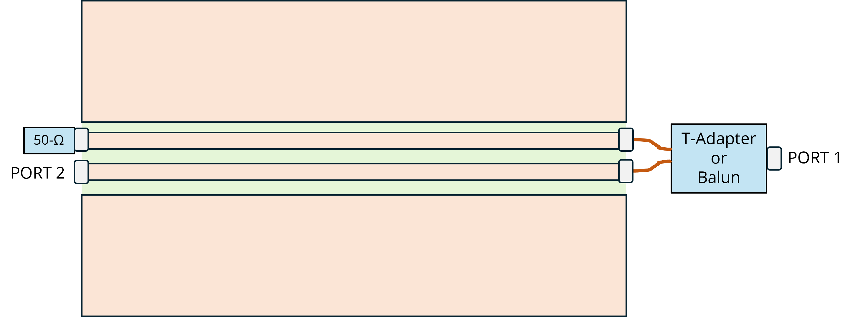
Step 2: Connect a 50-Ω terminator to one end of one of the traces. Connect the other trace at that end to Port 2 of the VNA. These 50-Ω resistances to ground are configured in the same manner as a pair of LISNs. The Port 2 measurement represents the voltage measured on one LISN.
Step 3: Connect a balun to the two traces on the other side of the board so that they can be driven differentially. Connect the balun input to Port 1 of the VNA. The setup is illustrated in the figure below.
Step 4: Make an S21 measurement. Since the LISN measures half the differential-mode signal, the value of S21 will be approximately -6 dB plus any gain or loss attributed to the balun. This is the starting point for measuring the differential-mode insertion loss.
Step 5: Replace the balun with a coaxial T-adapter. This sends the same Port 1 voltage to both traces.
Step 6: Make an S21 measurement. Since the LISN measures the common-mode signal, the value of S21 will be approximately -3.5 dB due to the fact that the common-mode termination impedance is 25 Ω and not 50 Ω. This is the starting point for measuring the common-mode insertion loss.
Step 7: Build a common-mode filter on the test fixture. Use copper tape, solder, and/or component leads to make connections. Use the knife to remove any unwanted copper.
Step 8: Use the configuration in Step 3 to measure S21. The difference (in dB) between this S21 measurement and the measurement in Step 3 is the differential-mode insertion loss. Make modifications to your filter if necessary to meet the specification.
Step 9: Use the configuration in Step 4 to measure S21. The difference (in dB) between this S21 measurement and the measurement in Step 4 is the common-mode insertion loss. Make modifications to your filter if necessary to meet the specification.
Step 10: Submit a report showing the design, design calculations, and the general approach used to ensure that the filter would work over the required frequency span.
Notes:
A variation of this exercise would be to short the Port 2 connector to ground and connect Port 2 of the VNA to an RF current probe around the wire pair connecting the balun to the board on the other end. This common-mode current is generated by the imbalance on the board and requires a different type of common-mode filter.
This could also be a student design competition.