
Chapter 9 Exercise: Designing and Building a Low-pass Filter
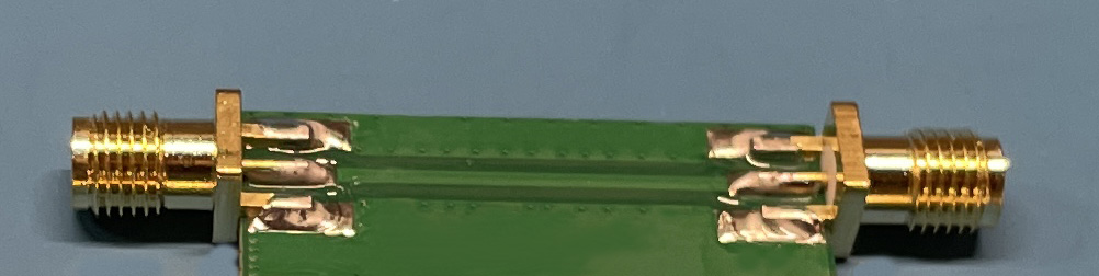
Students design and build a low-pass filter on a microstrip trace.
Preparation: Students are given a filter component kit with the parts they can use to build their filter. The kit should include the board that the students will solder components to. This board may be partially pre-assembled like the one in the figure, or the students may create their own microstrip trace as described in the procedure below. Students will be given a set of design parameters that their filter should meet. For example, "less than 2 dB attenuation below 5 MHz and greater than 20 dB attenuation from 30 to 200 MHz." They should have a preliminary design in mind before coming into the lab.
Equipment Required:
- vector network analyzer
- cables and adapters
- copper tape, utility knives, soldering iron
- filter component kit including:
- copper-clad board to build the filter on
- board-edge connectors
- filter components such as capacitors, inductors and/or ferrites with various values
Procedure:
Step 1: Design a filter to meet the specified requirements before coming into the lab.
Step 2: Use the utility knife to cut away unwanted copper on one side of the board to form traces and solder pads.
Step 3: Solder the board-edge connectors and components to the board.
Step 4: Measure the insertion loss from 1 MHz to 1 GHz.
Step 5: Repeat the steps above if necessary to meet the requirements.
Step 6: Submit a report showing the design, design calculations, and the general approach used to ensure that the filter would work at high frequencies.
Notes:
A sample lab exercise is provided here - Filter-Design-Lab020.pdf
This could also be a student design competition.