
Chapter 7 Lab Exercise: Mode Conversion Due to Changes in Cable-to-Cable Electrical Balance
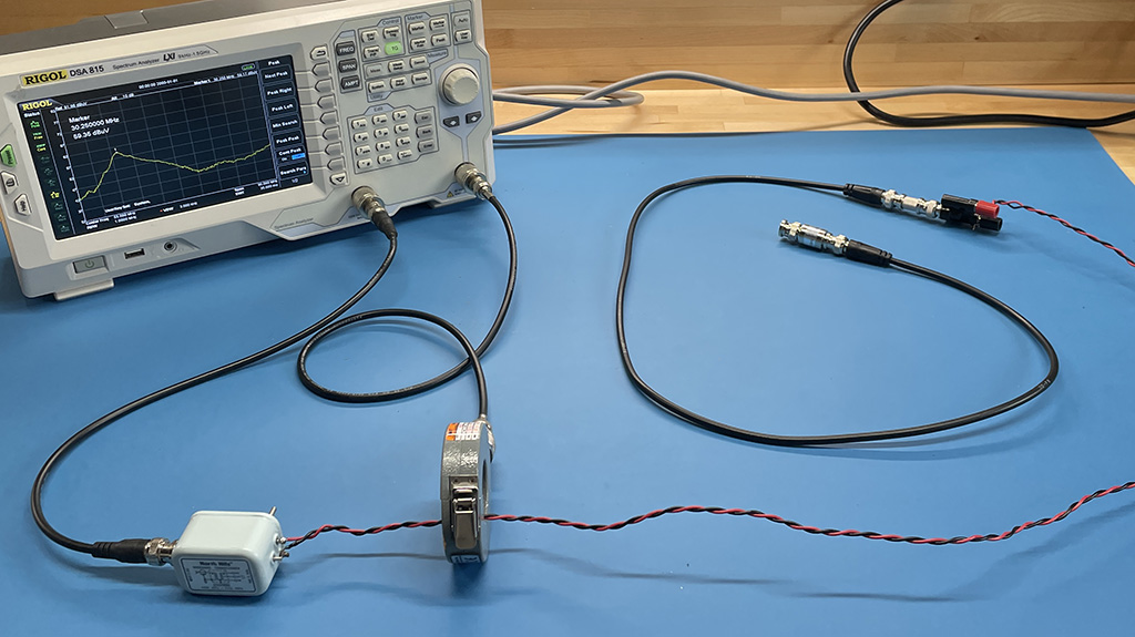
Common-mode current on cables is a major source of conducted and radiated emissions. Differential-mode signals can be converted to common-mode noise when their path of propagation experiences a change in electrical balance.
Preparation: Students need to become familiar with the definitions of differential-mode and common-mode as described in Chapter 7.
Equipment Required:
- vector network analyzer (or spectrum analyzer with a tracking generator)
- 2 coaxial cables (50-100 cm)
- 2 twisted or untwisted wire pair cables (same length as coax)
- RF current probe (30-100 MHz)
- balun or isolation transformer that works up to 100 MHz.
- snap-on ferrite cores (optional)
Procedure:
Step 1: Connect Port 1 of the VNA to one section of the coaxial cable. Connect the other end of the cable to the second coaxial cable using a barrel connector.
Step 2: Connect Port 2 to the RF current probe and place the probe around the first section of coaxial cable at a fixed and repeatable position. Terminate the second coaxial cable with a matched load. Record the peak amplitude and frequency of the measured common-mode current between 30 and 100 MHz. (This will be a small value.)
Step 3: Disconnect the second coaxial cable and connect the first coaxial cable to the twisted wire pair. Terminate the twisted wire pair with a matched load. Record the peak amplitude and frequency of the measured common-mode current between 30 and 100 MHz. The imbalance change at the connection creates a common-mode voltage that drives one cable relative to the other. A significant common-mode current should be detected.
Step 4: Place the balun on the Port 1 output of the VNA and use it to drive a twisted wire pair. Connect the other end of the cable to the second twisted wire pair and terminate it with a matched load.
Step 5: Connect Port 2 to the RF current probe and place the probe around the wire-pair cable at a fixed and repeatable position. Record the peak amplitude and frequency of the measured common-mode current between 30 and 100 MHz. (This will be a small value.)
Step 6: Disconnect the second twisted wire pair and replace it with a matched coaxial cable. Record the peak amplitude and frequency of the measured common-mode current between 30 and 100 MHz. The imbalance change at the connection creates a common-mode voltage that drives one cable relative to the other. A significant common-mode current should be detected.
Step 7: Try clamping a snap-on ferrite core around the cable at various positions. How much reduction in the common-mode current can be achieved this way?
Notes:
This exercise is similar to the previous exercise, replacing the test board with a second cable.
The common-mode current is proportional to the differential-mode voltage at the connection as well as the change in the imbalance. Both the balun and the different termination impedances alter this voltage between test set-ups. This voltage difference is easily calculated and can be accounted for when comparing the common-mode currents in the different test configurations.