EMC Design Myths
If an idea gets repeated often enough, people tend to accept it as fact. Here are some of the more infamous EMC design myths that refuse to go away.
90° corners in circuit board traces cause radiated emissions.
They don't. Etching problems? Not really. Signal integrity problems? Perhaps at data rates >50 Gbps.
References
How Interconnects Work: Minimal-reflection 90-degree bends in strip lines, Y. Shlepnev, March 2, 2021.
Should You Worry About 90 Degree Bends in Circuit Board Traces?, Eric Bogatin, Signal Integrity Journal, April 13, 2021.
Slaying the PCB 90⁰ Right-Angles Bend Dragon, Kella Knack, Altium Website, 2019.
PCB Routing Angle Myths: 45-Degree Angle Vs 90-Degree Angle, Zachariah Peterson, Altium Website, 2022.
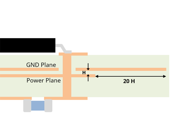
The 20-H Rule: The power plane should be 20 layer-spacings farther from the board edge than the ground plane in order to reduce radiated emissions.
As far as radiated emissions from a pair of planes, making the power plane smaller does not affect the peak emissions. It only changes the resonant frequency. If the power plane is sandwiched between two ground planes, emissions from the edge are negligible as long as the planes are well-connected in the general vicinity of the edge. There may be times when it is a good idea to keep all traces and planes away from the board edge (e.g., to prevent near-field coupling to objects adjacent to the edge). Nevertheless, there is no data that generally supports pulling the edge of the power plane away from the edge of the ground plane by any distance. Adhering to a 20-H rule is more likely to create a problem than it is to prevent one.
References
Practical analysis on 20H rule for PCB," Shinichi Ikami and Akihisa Sakurai, 2008 Asia-Pacific Symposium on Electromagnetic Compatibility and 19th International Zurich Symposium on Electromagnetic Compatibility, Singapore, 2008, pp. 180-183.
Analysis on the effectiveness of the 20-H rule for printed-circuit-board layout to reduce edge-radiated coupling, M. I. Montrose et. al., IEEE Trans. on EMC, vol. 47. no. 2, 2005. [Note: This paper goes out of its way to support the 20-H rule by focusing on the near field, and modeling strongly driven resonant structures. Even so, the data presented does not support the rule.]
20-H rule modeling and measurements, H. W. Shim and T. H. Hubing, 2001 IEEE EMC International Symposium. Symposium Record. International Symposium on Electromagnetic Compatibility, 2001, pp. 939-942.
Effects of 20-H rule and shielding vias on electromagnetic radiation from printed circuit boards, Huabo Chen and Jiayuan Fang, IEEE 9th Topical Meeting on Electrical Performance of Electronic Packaging, 2000, pp. 193-196.
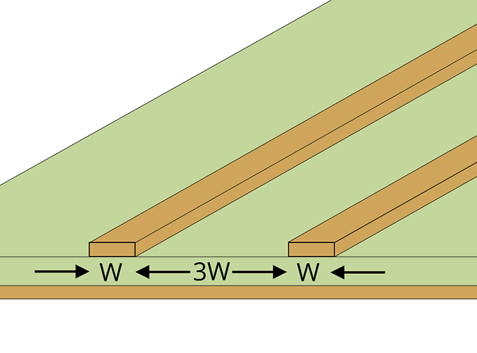
The 3W Rule: The edge-to-edge spacing between two parallel traces on a circuit board should be three times the trace widths.
This is generally described as a rule to prevent excessive crosstalk between signal traces. However, three coupling mechanisms can cause crosstalk, and none of them is strongly dependent on the trace width. Electric and magnetic-field coupling between microstrip traces both depend on the trace spacing relative to the trace height. In some cases, an argument could be made for a 2H or a 5H rule to set the spacing relative to the trace height. However, the amount of acceptable crosstalk is highly application-dependent. Mindlessly adhering to any spacing rule is not likely to yield optimum results. And setting the spacing based on the trace width makes no sense.
References
Electromagnetic Compatibility Course Notes, T. H. Hubing, LearnEMC, Chapter 6. [Note: This reference describes crosstalk calculations due to each of the EM coupling mechanisms.]
Crosstalk Calculator - Microstrip NEXT and FEXT Noise," Best Calculators Website. [Note: We are not endorsing this calculator, but it illustrates that simple first-order crosstalk calculations do not depend on the trace width.]
Stripline Crosstalk Calculator, All About Circuits Website. [Note: We are not endorsing this calculator, but it illustrates that simple first-order crosstalk calculations do not depend on the trace width.]
Is there another EMC design myth that you would like to see us address here? Let us know by sending an email to