Conductance

The term conductance can refer to any inverse resistance, G=1/R. However, it is generally applied to imperfect dielectrics in the same way that resistance is used to describe imperfect conductors. It is the ratio of the conduction current flowing in the dielectric between two conductors to the potential difference between those conductors.

Example 1: Conductance per Unit Length of a Coaxial Cable
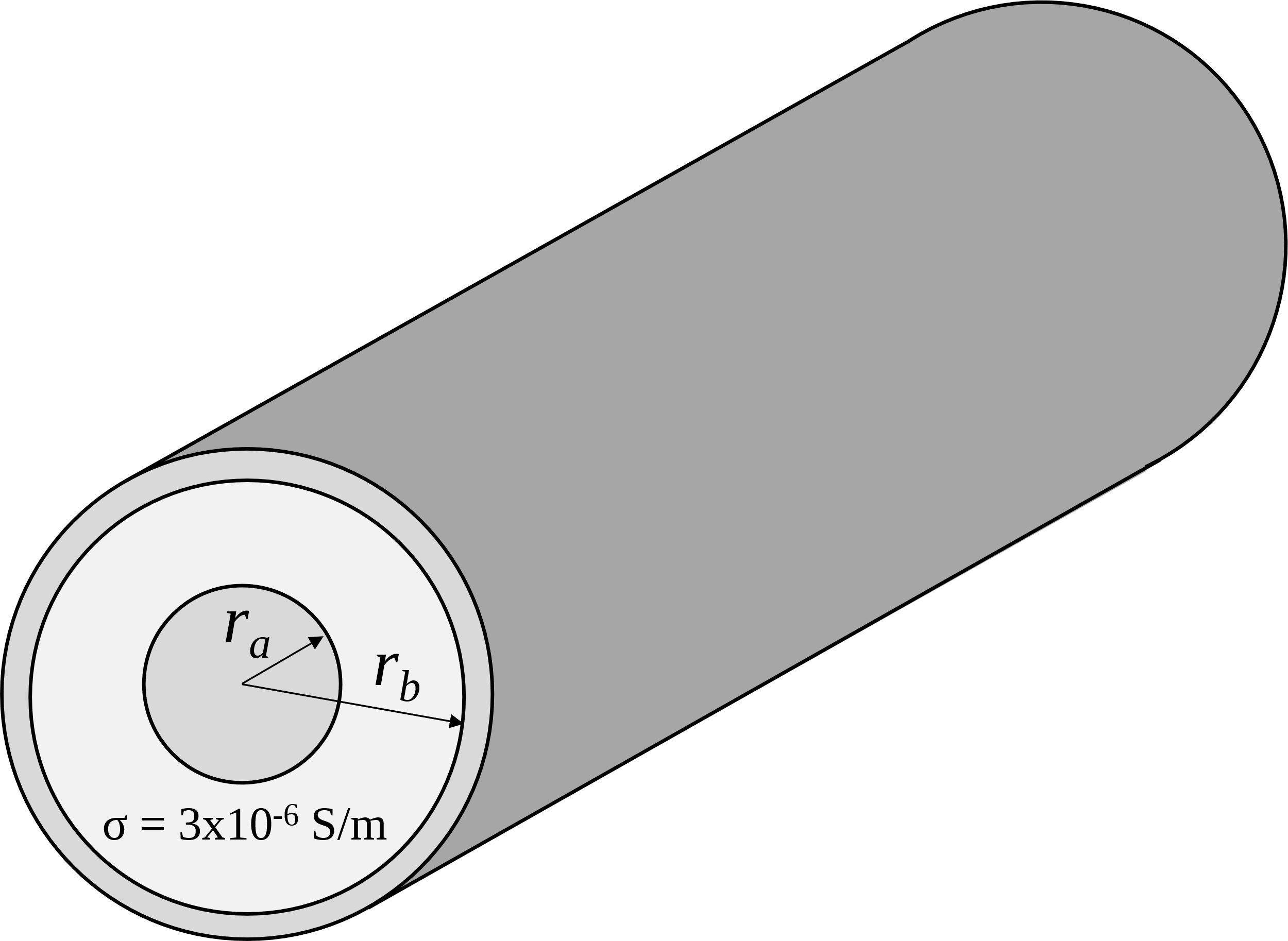
coaxial cable geometry

Determine the conductance per unit length of a coaxial cable with an inner conductor radius, ra, and an outer radius, rb. The dielectric between the two conductors has a conductivity, σ = 3 × 10-6 S/m.

If we assume a uniform current I flows between the two conductors, then the magnitude of the current density J MathType@MTEF@5@5@+= feaahWart1ev3aqatCvAUfeBSjuyZL2yd9gzLbvyNv2CaerbpbxzUb YuH52CaeXatLxBI9gBaebbnrfifHhDYfgaruatPjwzYfgDP9MBGmvz YLMzaibaiKc9yrVq0xXdbba91rFfpec8Eeeu0xXdbba9frFj0=OqFf ea0dXdd9vqaq=JfrVkFHe9pgea0dXdar=Jb9hs0dXdbPYxe9vr0=vr 0=vqpWqaaeaabaGaaiaacaqabeaadaabamaaaOqaamaaFiaabaGaam OsaaGaay51Gaaaaa@3A6D@ decreases as it moves from the inner conductor to the outer conductor because it is spread over an increasing area. By dividing the total current by this area, we obtain an expression for the current density,

J = I 2πr r ^ A/m 2 MathType@MTEF@5@5@+= feaahWart1ev3aaatCvAUfeBSjuyZL2yd9gzLbvyNv2CaerbpbxzUb YuH52CaeXatLxBI9gBaebbnrfifHhDYfgaruatPjwzYfgDP9MBGmvz YLMzaibaiKc9yrVq0xXdbba91rFfpec8Eeeu0xXdbba9frFj0=OqFf ea0dXdd9vqaq=JfrVkFHe9pgea0dXdar=Jb9hs0dXdbPYxe9vr0=vr 0=vqpWqaaeaabaGaaiaacaqabeaadaabamaaaOqaamaaFiaabaGaam OsaaGaay51GaGaeyypa0ZaaSaaaeaacaWGjbaabaGaaGOmaiabec8a WjaadkhacqqItecBaaWaaecaaeaacaWGYbaacaGLcmaacaaMf8Uaae yqaiaab+cacaqGTbWaaWbaaSqabeaacaqGYaaaaaaa@477E@

where r is the radial distance from the center of the cable and l is the length of the cable. The electric field is found by applying Ohm’s Law,

E = J σ = I 2πrσ r ^ V/m MathType@MTEF@5@5@+= feaahWart1ev3aaatCvAUfeBSjuyZL2yd9gzLbvyNv2CaerbpbxzUb YuH52CaeXatLxBI9gBaebbnrfifHhDYfgaruatPjwzYfgDP9MBGmvz YLMzaibaiKc9yrVq0xXdbba91rFfpec8Eeeu0xXdbba9frFj0=OqFf ea0dXdd9vqaq=JfrVkFHe9pgea0dXdar=Jb9hs0dXdbPYxe9vr0=vr 0=vqpWqaaeaabaGaaiaacaqabeaadaabamaaaOqaamaaFiaabaGaam yraaGaay51GaGaeyypa0ZaaSaaaeaadaWhcaqaaiaadQeaaiaawEni aaqaaiabeo8aZbaacqGH9aqpdaWcaaqaaiaadMeaaeaacaaIYaGaeq iWdaNaamOCaiabjoriSjabeo8aZbaadaqiaaqaaiaadkhaaiaawkWa aiaaywW7caqGwbGaae4laiaab2gaaaa@4DCB@ .

and the voltage between the two conductors is found by integrating the electric field,

V ab = r a r b I 2πrσ dr= I 2πrσ ln r b r a volts. MathType@MTEF@5@5@+= feaahWart1ev3aaatCvAUfeBSjuyZL2yd9gzLbvyNv2CaerbpbxzUb YuH52CaeXatLxBI9gBaebbnrfifHhDYfgaruatPjwzYfgDP9MBGmvz YLMzaibaiKc9yrVq0xXdbba91rFfpec8Eeeu0xXdbba9frFj0=OqFf ea0dXdd9vqaq=JfrVkFHe9pgea0dXdar=Jb9hs0dXdbPYxe9vr0=vr 0=vqpWqaaeaabaGaaiaacaqabeaadaabamaaaOqaaiaadAfadaWgaa WcbaGaamyyaiaadkgaaeqaaOGaeyypa0Zaa8qmaeaadaWcaaqaaiaa dMeaaeaacaaIYaGaeqiWdaNaamOCaiabjoriSjabeo8aZbaaaSqaai aadkhadaWgaaadbaGaamyyaaqabaaaleaacaWGYbWaaSbaaWqaaiaa dkgaaeqaaaqdcqGHRiI8aOGaaGjbVlaadsgacaWGYbGaeyypa0ZaaS aaaeaacaWGjbaabaGaaGOmaiabec8aWjaadkhacqqItecBcqaHdpWC aaGaaGjbVlGacYgacaGGUbWaaeWaaeaadaWcaaqaaiaadkhadaWgaa WcbaGaamOyaaqabaaakeaacaWGYbWaaSbaaSqaaiaadggaaeqaaaaa aOGaayjkaiaawMcaaiaaywW7caqG2bGaae4BaiaabYgacaqG0bGaae 4Caiaac6caaaa@654B@

The conductance per unit length is the ratio of the current per unit length to the voltage,

G= 2πσ ln r b r a S/m. MathType@MTEF@5@5@+= feaahWart1ev3aaatCvAUfeBSjuyZL2yd9gzLbvyNv2CaerbpbxzUb YuH52CaeXatLxBI9gBaebbnrfifHhDYfgaruatPjwzYfgDP9MBGmvz YLMzaibaiKc9yrVq0xXdbba91rFfpec8Eeeu0xXdbba9frFj0=OqFf ea0dXdd9vqaq=JfrVkFHe9pgea0dXdar=Jb9hs0dXdbPYxe9vr0=vr 0=vqpWqaaeaabaGaaiaacaqabeaadaabamaaaOqaaiaadEeacqGH9a qpdaWcaaqaaiaaikdacqaHapaCcqaHdpWCaeaaciGGSbGaaiOBamaa bmaabaWaaSaaaeaacaWGYbWaaSbaaSqaaiaadkgaaeqaaaGcbaGaam OCamaaBaaaleaacaWGHbaabeaaaaaakiaawIcacaGLPaaaaaGaaGzb VlaabofacaqGVaGaaeyBaiaab6caaaa@4A62@

Note the similarity between the expression for the conductance above and the expression for the capacitance per unit length of a coaxial cable,

C= 2πε ln r b r a F/m. MathType@MTEF@5@5@+= feaahWart1ev3aaatCvAUfeBSjuyZL2yd9gzLbvyNv2CaerbpbxzUb YuH52CaeXatLxBI9gBaebbnrfifHhDYfgaruatPjwzYfgDP9MBGmvz YLMzaibaiKc9yrVq0xXdbba91rFfpec8Eeeu0xXdbba9frFj0=OqFf ea0dXdd9vqaq=JfrVkFHe9pgea0dXdar=Jb9hs0dXdbPYxe9vr0=vr 0=vqpWqaaeaabaGaaiaacaqabeaadaabamaaaOqaaiaadoeacqGH9a qpdaWcaaqaaiaaikdacqaHapaCcqaH1oqzaeaaciGGSbGaaiOBamaa bmaabaWaaSaaaeaacaWGYbWaaSbaaSqaaiaadkgaaeqaaaGcbaGaam OCamaaBaaaleaacaWGHbaabeaaaaaakiaawIcacaGLPaaaaaGaaGzb VlaabAeacaqGVaGaaeyBaiaab6caaaa@4A35@

The procedure for determining the capacitance between conductors is analogous to the method used to determine conductance. Instead of beginning with an electric flux due to static charges, we start with an electric current. Instead of a variable ε, which is the ratio of electric flux to electric field, we use the variable σ, which is the ratio of electric current to electric field. Generally, any expression for the capacitance of a configuration can be converted to an expression for the conductance by making the substitutions C→G and ε→σ.