Common-Mode Filtering
The term “common mode” is used to describe two very different phenomena in transmission lines with three or more conductors. The common-mode current can refer to the current propagating in one direction on the signal conductors and returning on the "ground" conductor. Or, it can refer to the current flowing in one direction on all the conductors without a nearby return conductor. Both types of common-mode current can contribute to conducted emissions, but radiated emissions are dominated by the common-mode current that flows in the same direction on all conductors.
Filtering Balanced Three-Conductor Lines
Consider the conducted emissions noise source illustrated in Figure 1(a). The switching of a flyback converter generates a time-varying voltage between the hot and neutral conductors of the device’s power input. This voltage appears across the 50-Ω resistances of the two LISNs used for the conducted emissions measurement. The hot and neutral conductors have the same impedance to ground in the device under test, the power cord, and the LISNs. Therefore, the system is balanced, and the switching source can be modeled using the differential-mode equivalent source shown in Figure 1(b).
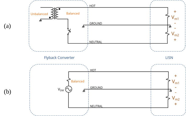
Figure 1: Model of conducted emissions generated by a flyback converter.
Note that the LISN voltages are defined relative to ground, so differential-mode noise currents flowing into the hot side of LISN 1 and out of the neutral side of LISN 2 generate measurement voltages that have the same magnitude, but opposite polarity. In this case, the differential-mode voltage measured by the LISNs is,
(1)
The common-mode voltage measured by the LISNs is,
(2)
If Vm1 is above the conducted emissions limit, filtering may be required to reduce it. Suppose we attempt to reduce the amplitude of Vm1 using the filter capacitor shown in Figure 2. If this capacitor has an impedance well below 50 W at the measurement frequency, it diverts current away from LISN 1 and successfully reduces Vm1. However, this current is still routed through Vm2. In fact, Vm2 is likely to be higher than it was without the filter, causing the product to be further over the limit.
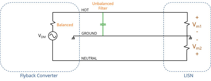
Figure 2: An unbalanced filter in a balanced system.
If the source impedance and the filter impedance are both much less than 50 Ω at the measurement frequency, the differential-mode voltage measured by the LISNs is,
(3)
The common-mode voltage measured by the LISNs is,
(4)
In general, applying an unbalanced filter to a balanced system forces a mode conversion that can have undesirable consequences. For this reason, filters in balanced systems should be balanced.
Consider the balanced filter design in Figure 3. Both power conductors are filtered using the same impedance to ground. Both Vm1 and Vm2 are reduced by the same amount. There is no conversion from differential mode to common mode.

Figure 3: A balanced Y-capacitor filter in a balanced system.
Capacitors that connect balanced pairs of power conductors to ground are called Y-capacitors. However, for differential-mode noise in a balanced system, it is not necessary to connect any of the filter elements to ground. A single capacitor with half the nominal value of the Y-capacitors between the hot and neutral wires would provide the same insertion loss. Capacitors that connect directly between the two power conductors in a balanced system are called X-capacitors. Figure 4 shows an X-capacitor filter.

Figure 4: A balanced X-capacitor filter in a balanced system.
The source impedance of a power converter can be a very small value. In this case, shunt capacitors may not provide enough insertion loss to meet a conducted emissions requirement. To achieve higher insertion loss, second or third-order filters can be applied. Figure 5 shows a third-order pi-filter applied in a balanced system. Note that both sides of the filter maintain the same impedance to ground.
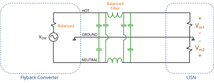
Figure 5: A balanced third-order filter.
If the source of the noise drives both power conductors relative to the LISN ground, it will have a common-mode component. Suppose the source of the conducted emissions is switching noise that drives a heatsink relative to circuit board ground on the secondary side of the transformer, as illustrated in Figure 6.
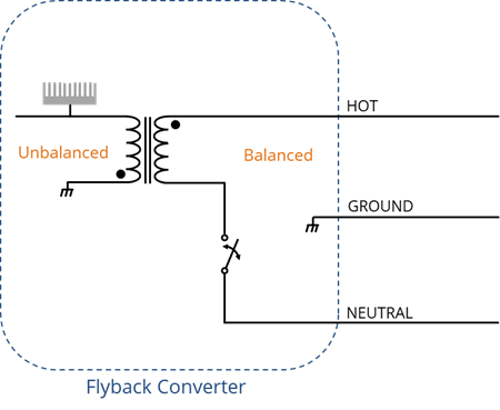
Figure 6: An unbalanced noise source in a flyback converter.
The voltage between the heatsink and circuit board generates electric field lines as illustrated in Figure 7. If the board and the heatsink do not have the same impedance to the chassis ground, then the number of field lines emanating from the heatsink is not equal to the number of field lines terminating on the circuit board. This is an unbalanced source relative to chassis ground, and it produces a voltage that drives the power lines relative to the chassis ground.
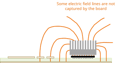
Figure 7: Electric field lines between a heatsink and circuit board.
This noise source drives the balanced power cord and LISNs with a common-mode voltage that can be modeled as illustrated in Figure 9.29. Note that the common-mode noise currents flow into the positive sides of both LISNs to the LISN ground. Common-mode currents generate voltages that have the same magnitude and the same polarity in both LISNs. Since the hot and neutral inputs still have the same impedance to ground, the conducted emissions source is still balanced.
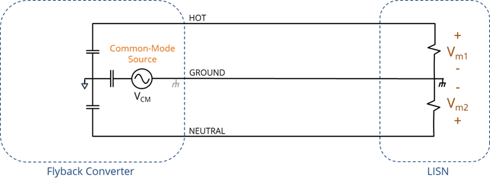
Figure 8: Model of a common-mode conducted emissions source.
Note that the balanced filters in Figures 3 and 5 attenuate common-mode noise as well as differential-mode noise. In many cases, the two filter inductors in Figure 5 are replaced with a common-mode choke. The common-mode choke provides a significant impedance (inductance) to common-mode currents. Differential-mode currents, on the other hand, see very little inductance.

Figure 9: A common third-order filter for balanced power inputs.
The power currents produce magnetic fields in the ferrite core of a common-mode choke that cancel each other. Because of this, common-mode chokes can handle much higher power currents than similarly sized uncoupled inductors without saturating. This means that, for a given current rating, a common-mode choke is typically much smaller than two uncoupled inductors. The filter in Figure 9 relies on the X-capacitors to provide most of the differential-mode attenuation. The common-mode choke and the Y-capacitors provide the common-mode attenuation.
Filtering Unbalanced Three-Conductor Lines
AC power inputs and isolated DC power inputs are typically balanced. However, many devices have unbalanced power inputs. Consider the buck converter input illustrated in Figure 10. Note that the impedance-to-ground of the two power phases is not the same. In this example, VBATT- is shorted to the frame ground, making the power input perfectly unbalanced. As indicated by the model in Figure 10(b), all of the switching noise appears across Vm1 while Vm2 is zero.
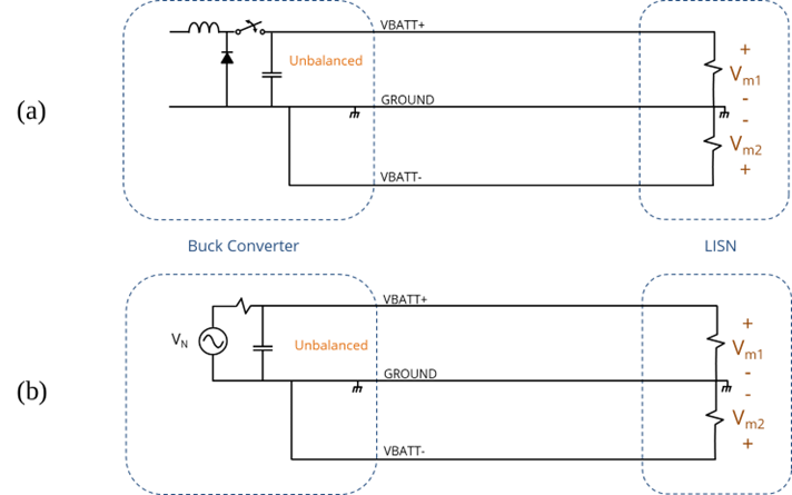
Figure 10: Model of conducted emissions generated by a buck converter.
Applying the same modal decomposition that we applied in the previous example, the differential-mode voltage measured by the LISNs is,
(5)
The common-mode voltage measured by the LISNs is,
(6)
It’s tempting to conclude that both common-mode and differential-mode filtering are required. However, in this case, the modal decomposition of the LISN voltages is misleading. In this example, there is only one source, and it is driving VBATT+ relative to the chassis ground. The VBATT+ side requires filtering; the VBATT- side does not.
A common-mode choke would force noise currents to return on the VBATT- wire instead of the GROUND wire. This would create a negative Vm2 voltage and nominally reduce the common-mode component of the noise, but it would not necessarily reduce Vm1. In most cases, a common-mode choke is not appropriate for filtering unbalanced power inputs.
Figure 11 shows a filter more appropriate for unbalanced power inputs like the one in Figure 10. The power conductor being driven by the switching noise is filtered to the chassis ground. The other power conductor (shorted to the ground) does not require any filtering as long as the short is made near the power connector. If some noise is picked up between the shorting point and the connector, then filtering (e.g., a capacitor to chassis ground) may be necessary.
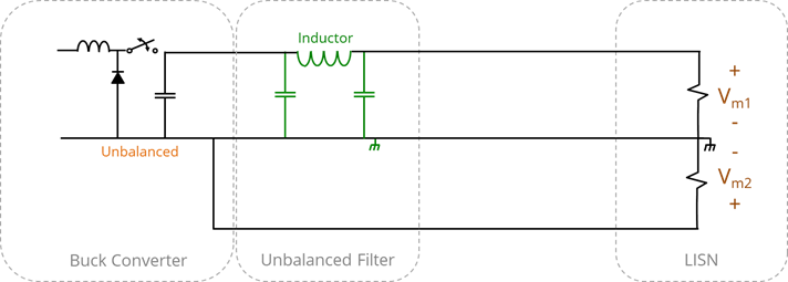
Figure 11: Filtering for an unbalanced power input.
In some devices with unbalanced power inputs, VBATT- is not shorted to the ground. For example, in devices that require DC isolation between the power ground and the chassis, VBATT- might connect to the circuit board’s power return plane without connecting directly to the chassis ground. In these cases, there are two approaches that generally work well for filtering the power input.
- Make the power input balanced and use a balanced filter.
- Make the power input very unbalanced and filter the side with the higher impedance to ground.
The second approach is illustrated in Figure 12. In this figure, VBATT+ connects to the switch and has no low-impedance path to the chassis. VBATT- connects to the current-return plane on the circuit board. This plane has a large surface area and a relatively low impedance to the chassis at high frequencies. To emphasize the imbalance, there is another plane on the board under the connector (usually labeled chassis ground). Several capacitors make a good high-frequency connection between the two planes. At the measurement frequencies, this power input is very unbalanced and can be filtered in the same manner as the non-isolated power input in Figure 1.
.
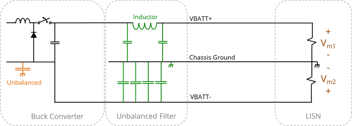
Figure 12: Filtering for an unbalanced power input with an isolated chassis ground.
In most situations where power input is both isolated and unbalanced, it is best to emphasize the imbalance by establishing a good high-frequency connection between the “circuit ground” and the chassis ground. A small voltage difference (e.g., 1 mV) between two relatively large conductors can result in unacceptable conducted and radiated emissions.
Filtering Balanced Two-Conductor Lines
Two-conductor transmission lines can also carry a common-mode current. If the power cord doesn’t have a ground wire, the common-mode current returns as a displacement current and/or a conduction current on nearby metal surfaces such as the metal table-top used in many standard EMC measurements.
Whether the power cord has two conductors or three conductors, the sources of common-mode and differential-mode noise are basically the same. From a filtering perspective, the most significant difference is that at least part of the common-mode current path includes a self- or mutual capacitance. This capacitance limits the common-mode current at low frequencies, so the filtering is mostly needed at high frequencies. Also, filters designed for resistive sources and loads may no longer be appropriate when the return path is capacitive.
Figure 13 illustrates appropriate filtering for products with balanced power inputs and a two-conductor power supply. In Figure 13(a), the product has a metal enclosure. Since the metal enclosure captures most of the field lines from an unbalanced source, common-mode filtering can return these noise currents to the enclosure with a chassis ground connection.
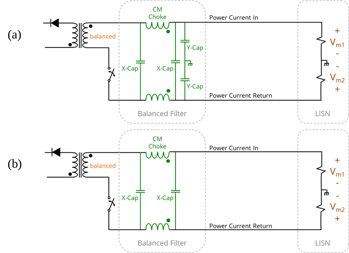
Figure 13: Filtering for a balanced power input with a two-conductor power supply.
Figure 13(b) shows a filter for a product with no metal chassis or enclosure. In this case, there is no chassis ground, and Y-capacitors cannot be used to reduce common-mode noise. This filter relies solely on the choke to provide common-mode filtering.
In products without a metal chassis, the common-mode current return path is capacitive at frequencies below the first cable resonance. Inductive chokes shift these resonant frequencies lower without necessarily providing any overall attenuation. In most situations where a common-mode choke is used without Y-capacitors to chassis ground, the ferrite material in the choke needs to provide high-frequency loss. Lossy chokes are widely available and provide attenuation similar to ferrite cores. Like ferrite cores, it is important to choose a choke that is effective at the frequencies where common-mode attenuation is required.
Filtering Unbalanced Two-Conductor Lines
Most low-voltage DC-to-DC converters have unbalanced power inputs. If these converters are fed by balanced two-conductor power lines, half the differential switching noise voltage they create is converted to a common-mode voltage that drives the power line relative to the circuit board. In these situations, the first priority is to filter the differential-mode switching noise with an unbalanced filter. If the differential-mode noise is low enough by the time it reaches the power line, the mode conversion due to the change in balance at the connector won’t be important.
Small devices in plastic enclosures (with all wired connections on one side of the board) tend to be weak sources of common-node current because there is nothing of significant size that can be driven relative to the attached wires. In these boards, differential-mode filtering is usually all that is required. This can be accomplished with a simple pi-filter referenced to the circuit board ground as illustrated in Figure 14.
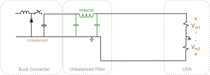
Figure 14: Filtering for an unbalanced power input with no chassis.
If the device with an unbalanced power input has a metal chassis, the chassis needs to be connected to the circuit board’s PCB EMC ground near the connector as described in the grounding tutorial. In this case, the filter shown in Figure 14 is still appropriate.
Larger devices in plastic enclosures are capable of generating significant common-mode voltages directly. An example of this would be a circuit board with a very large heatsink, as illustrated in Figure 9.36. In this situation, the lines of electric flux that are not captured by the board represent a self-capacitance. This is effectively a capacitance to the LISN’s ground reference.
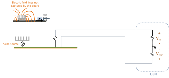
Figure 15: A common-mode source in a device with no chassis.
In this situation, the source drives the entire board relative to the LISN ground. Filtering the powerline wires back to the board doesn’t help, because it is the board’s potential relative to ground that drives the common-mode current. Electrical balance is not a factor because the common-mode current is not due to mode conversion. It is the direct result of a common-mode voltage source.
Without a chassis to provide an alternative path for the noise current, there is really only one good filtering option. As illustrated in Figure 16, we can use Y-capacitors to give both power wires the same low impedance to the board ground. This alone doesn’t reduce the common-mode current, but it makes the power input look balanced at the noise frequencies. With a balanced power input, we can use a lossy common-mode choke to reduce the amount of common current generated by the common-mode voltage source.
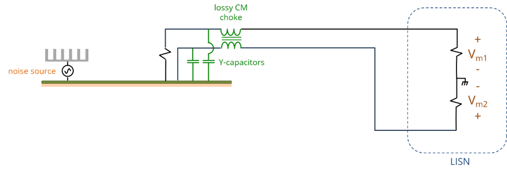
Figure 16: Filtering a common-mode source in a device with no chassis.
Note that it is very important that no Y-capacitors be placed on the LISN side of the choke. Y-capacitors in this position would allow the common-mode current to flow around the choke. Also, the choke must provide a high-frequency resistance (not just an inductance) to the common-mode current. Part of the common-mode current path is already capacitive. Putting a low-loss inductance in this path could create an unwelcome resonance or shift an existing resonance to a new frequency.
References
[1] Mix, Filter Design Techniques: Analog and Digital Filters, Frequency Selective and Matched Filters, Adaptive Matched Filter and Template Design, 2nd ed., 2024, ISBN: 979-8336093834.
[2] L. Ozenbaugh and T. M. Pullen, EMI Filter Design, 3rd ed., CRC Press, 2012.
[3] Adamczyk, Principles of Electromagnetic Compatibility – Laboratory Exercises and Lectures, John Wiley and Sons, 2024, Chapter 5.