Magnetic Field Coupling
Magnetic field coupling (also called inductive coupling) occurs when energy is coupled from one circuit to another through a magnetic field. Since currents are the sources of magnetic fields, this is most likely to happen when the impedance of the source circuit is low.
Consider the two circuits sharing a common return plane shown in Fig. 1. Coupling between the circuits can occur when the magnetic field lines from one of the circuits pass through the loop formed by the other circuit. Schematically, this can be represented by a mutual inductance between the two signal wires as shown in Fig. 2.
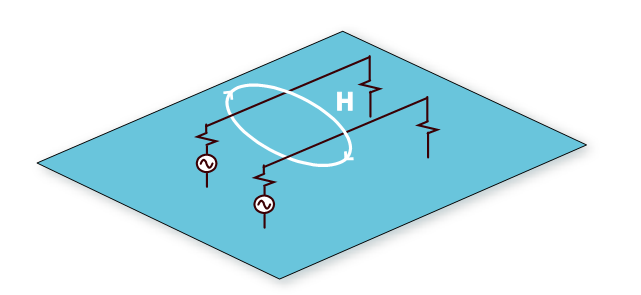
Fig. 1: Two circuits above a signal return plane.
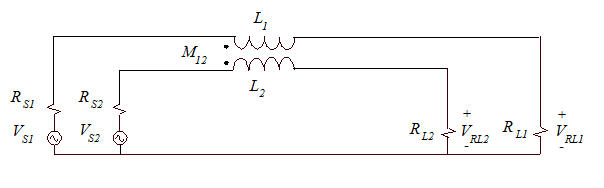
Fig. 2: Schematic representation of the circuits in Fig. 1 including inductive coupling.
In most cases, a convenient closed-form equation for calculating the mutual inductance will not be available. However, we can often estimate the mutual inductance by estimating the percentage of the total magnetic flux generated by the first loop that couples the second loop. For example, suppose the two wires in the example above are 20 mm above the plane and separated by 5 mm. We could visualize the magnetic flux lines that wrap the current in line 1 as shown in Fig. 3.
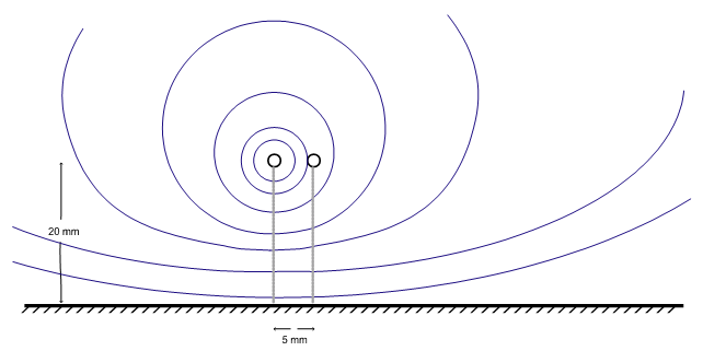
Fig. 3: More intuitive schematic representation of the circuits in Fig. 1.
If the wire radius in the example above is 0.6 mm, we could calculate the self inductance of the source circuit using the equation for the inductance per unit length of a wire over a conducting plane,
. (1)
The self inductance is the total flux divided by the current while the mutual inductance is the flux that couples both loops divided by the current. Therefore the mutual inductance can be expressed as a fraction of the self inductance,
. (2)
Based on the rough sketch in Fig. 3, we might estimate that somewhere between 50% and 80% of the flux couples both circuits. If we were to assume 60%, then our estimate of the mutual inductance would be,
. (3)
Of course, there are more accurate ways of determining the mutual inductance between two circuits. Electromagnetic modeling software is often used for this purpose when it is necessary to determine crosstalk levels more precisely. There are also a number of closed-form equations that can be applied to specific geometries. In fact, for the case of two thin wires above an infinite ground plane, there is a relatively simple closed form expression [1],
(4)
where h1 and h2 are the heights of the two wires above the plane, s is the distance between the two wires and the wire radius is small relative to the height and separation. Applying this equation to the example above,
. (5)
The difference between the estimate (3) and the calculation in (5) is less than 2 dB. Estimates within a few dB are usually accurate enough to indicate whether a potential crosstalk problem exists.
To calculate the crosstalk due to magnetic field coupling, we start with the current in the source circuit, since the current is the source of the magnetic field. The voltage induced in the second circuit can be expressed as,
. (6)
VLOOP2 is the voltage induced in the entire loop of the circuit. The fraction of this voltage that will appear across the load can be expressed as,
. (7)
Since, I1 = VRL1/RL1, the crosstalk due to magnetic field coupling can be expressed as,
. (8)
Example 6-1: Calculating the crosstalk between two 50-ohm circuits
For the circuit illustrated in Figs. 1 and 2, assume the signal wires are 16 cm long. Assume the wire radius is 0.6 mm, the height is 20 mm, and the spacing between the wires is 5.0 mm as illustrated in Fig. 3. Let RS1 = RS2 = 10 ohms and RL1 = RL2 = 50 ohms. Calculate the crosstalk due to magnetic field coupling between these circuits at 10 MHz.
The inductance of each circuit and the mutual inductance between the two circuits per unit length are given in (1) and (5). Multiplying by the length of the circuit, we get
. (9)
The impedance of L11 and L22 at 10 MHz is jωL = 8 ohms, which is small relative to the resistance each circuit, so we can ignore it. Substituting the circuit values into Equation (8) we get,
. (10)
It is helpful to observe how changing the various circuit parameters would have changed the coupling. For example, doubling the frequency would have doubled the crosstalk (i.e. at 20 MHz, the calculated crosstalk would be -17 dB). Both inductive coupling and capacitive coupling are proportional to frequency for the weak coupling case with resistive loads.
Doubling the load resistance of the source circuit would also have nearly cut the current in the source circuit by one half, which would have reduced the crosstalk by 6 dB. In this example, doubling the load resistance of the victim circuit would have had relatively little effect on the crosstalk, since it most of VLOOP2 was already dropped across the load.
The other important parameter in this example is the mutual inductance, M12. Reducing the value of M12 would reduce the crosstalk proportionally. Moving the wires farther apart is one way to reduce the value of M12. Bringing them closer to the plane is another. Generally, any change that reduces the self-inductance of either loop is likely to reduce the mutual inductance between them.
References
[1] C. R. Paul, Introduction to Electromagnetic Compatibility, 2nd Ed., Wiley Series in Microwave and Optical Engineering, 2006.